Friday, 12 June 2015

vwcdpic for avr (arduino) and attiny


Porting to arduino's or AVR?

I sell on Tindie
while back I read on hackaday forums about guy who ported some C code for avr (for seeduino mega) originaly ported from k9spud vwcdpic ...

back then I was really bad in arduinos or any coding for mcus, so I was unable to make it work on normal *duino .... 

then i find this post of shyd version of emulator 

and now i'm less lame so I did it :)

Problem


for protocol read shyd post, it preaty explain everything about pulses etc ....

problem of porting avr vwcdpic code to arduino:

- ICP pin need to be accesible
- one 16bit timer (attiny hase 2x8bit timer)
- two timers with CTC (atmega8 does not have ctc)

ICP pin


basicaly external logical change interupt on pin called ICP which is directly "wired" to timer1( ICP as INPUT CAPTURE PIN), this pin is not wired on ATMEGA arduino boards (mega1280 and 2560). This is why guy on hackaday use seeduino...
On normal arduino duemilanove or UNO is ICP1 on digital pin 8, so this will work perfectly on duemilanove/uno and also old atmega8 chips.

Also its posible to reprogram code to use standard INTx interupr as I use in attinyx5 version of this code.

16bit timer

this timer is used to measuring pulses length of data send by head unit, more in post here and here.

In original code is set to tick every 0.5us, its 16bit timer, max value of 65536 which corespod to 32000something ms ~ 32second, which is fine, perfect resolution, we can surely set input buffer to zero if this timer overflow (no logical change on ICP pin for 32 seconds...)

but if we have 8bit timer like in attiny85 (255tics to overflow which is 128us if I'm not mistaken) and want to have same resolution as with 16bit timer, to avoid recalculation of tics per pulse.... we must catch overflows and count them, then just calculate pulse lenght as 255*overflows+actual timer

2 timers for timing output packets

next challenge was timing for output to head unit, lets call it packet of 8 bytes, with this timing:

50ms between pakets
at last 700us between bytes in packets (in vwcdpic is note that same head units cant store it if timing was 350us, in some other sources on net, timing is 874us ... but 700us works for me...)

in original code timer0 and timer2 are 8bit timers, in original code used for:

- 700us timing between bytes
- 50ms timing between packets and to cound seconds ... (20x50ms = 1000ms = 1s)

this is no problem on atmega168/328 but its problem on atmega8 and attiny85

atmega8 has no compare register for timer0, attiny85 hase just two 8bit timers/counters

Timer0 on atmega8


atmega has timer0 without CTC mode, no compare possible , so we must make it work other way around, we have overflow:
-  so I set OVF bit to allow execution of OVF runtime routine
- set timer to 4us tics, this make it overflow each 1024us
- initialize timer with value of 6 which make it overflow after 1000us
- in overflow routine  timer is initialize with 6 to overflow again after 1000us


Attiny85 and two 8-bit timers


timer1 is used for input capture with combination on int0 external interrupt and counting overflows... no big deal

timer0 must be used to timing of 1ms tics for seconds count and for output packets timing, so what I did was really easy, and I go to rewrite all code also for atmegax chips to use it. I set timer to tic every 1us, set compare register to be 100, so its fire compare routine every 100us. In this routine I do counting, 50 count to make original code happy ...
and to count to 7 or to 50 to make output packets timing work ...

second timing for output packets is set directly in code which handle sending packet, if it reach end, it will set 50 to wait 50ms between packets, if it just sent less then eirhts byte it set 7, so next byte is flush out after 7 overflows of timer0 = 700us

Output to headunit

output to head-unit is SPI, it's nothing new, but this didn't work for 16Mhz arduinos (simply it's to fast), so software handling of this is used. I like crystal version more over internal RC oscillators becose this is in car application where external crystal should by better, but I do not test or read any paper on this, so correct me please if I'm wrong.

also attiny has no SPI dedicated pins, it it's capable of use some internal magic to have SPI by HW but it use pin which is also INT0, and this we need... so using software here is only option

Serial comunication


Original vwcdpic used 9600bauds serial communication for PJRC player, which I do not know if it is around anymore, but it was also in avr code, so I leave it there just make it fully backward compatible, with "in compile time" configurable #define PJRC, becose this make emulator constantly send "mode" on serial line, which may toggle  "mode" on mpd  each second or so ...

also add option to support shyd version of serial communicaton to control mpd over serial with mpc and python, and receive info from mpd like mode, disc and track number. This is configurable in compile time with  uncommenting #define DISC_TRACK_NUMBER_FROM_MPD, #define JUST_HEX_TO_SERIAL and commenting out #define PJRC

attiny85 use TinyDebugSerial library which is oneway library but it didn't use any timer, so I can use both(timers).

 Mpd control

I made some changes of shyd python script to control mpd both with just hex and pjrc commands , this are on github. Also mpd_control_vwcdpic.py should support original pic version of vwcdpic, but I have no time to check it.

I make this pythons script handle next/previos CD which are send (as I know) only from audi chorus 1 with enabled CD input and audi concert 1.

video of all of this is here:


how to wire it?

arduino duemilanove/uno or atmega8
RADIO PIN -> arduino pin (chip pin) <- computer
     DataOut -> digital 8      (14)
       DataIn -> digital 13    (19)
         Clock -> digital 12    (18)
                        digital 0      (2)  <------------ serial TX
                        digital 1      (3)  <------------ serial Rx
 
attiny85:
RADIO PIN -> attiny pin <- computer
     DataOut -> 7
       DataIn -> 6
         Clock -> 5
                        2  <------------- serial RX

Future

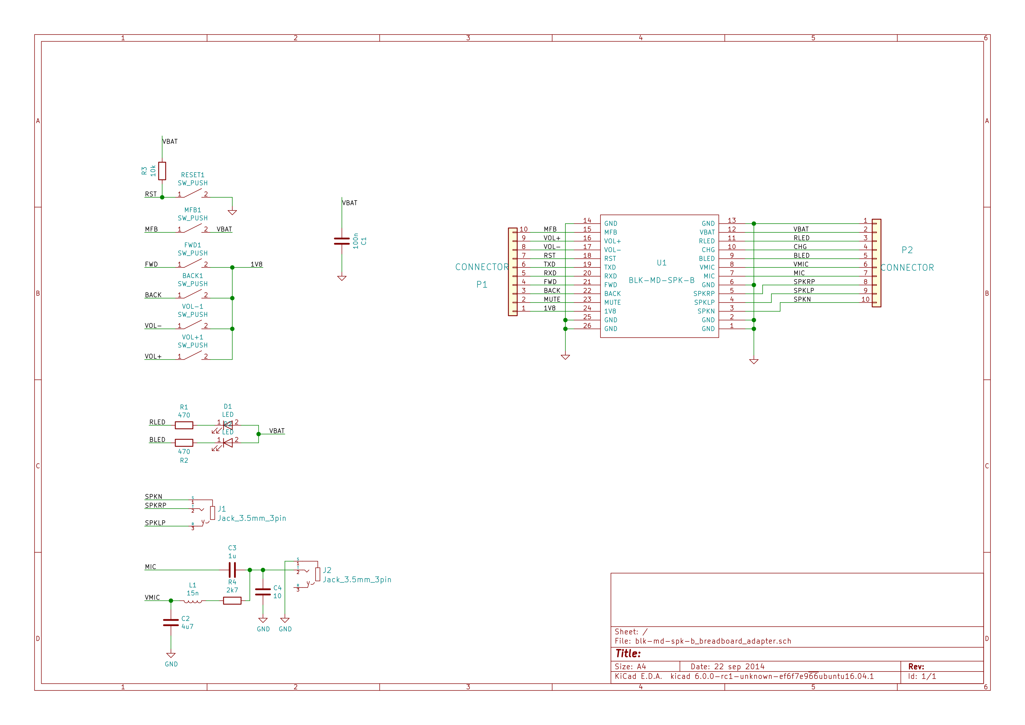
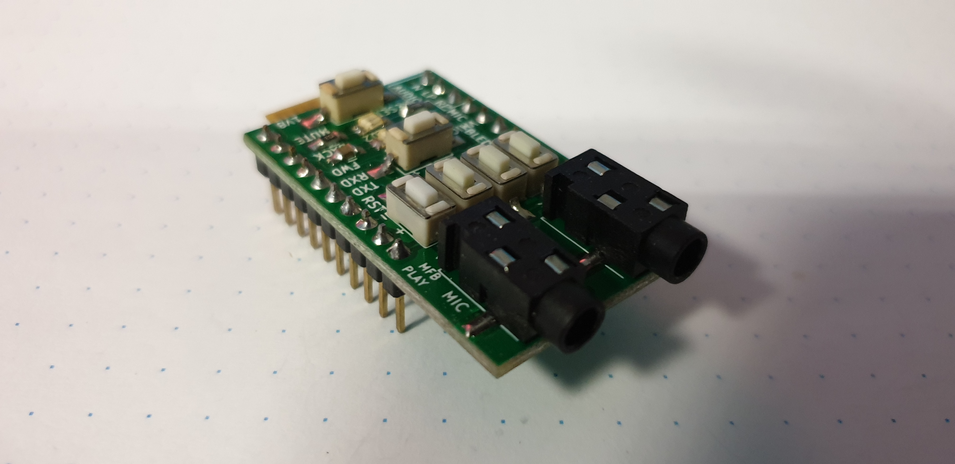
 Bluetooth... clearly, I made it here, with blk-md-spk-b module, but it has problem handling calls, so I ordered xs3868 and made kicad module and library. So next to make some breakout boards and try it.

 Next stage is implementing SOYO-BT24G03 (made kicad library, module, get AT command set ) which has support of more profiles (also address book ;) ) and also has support of sdcard and usb :) 

BM20 it will be ;)

Links 

arduino,atmegaX8,atmega8 port of  k9spud vwcdpic
port of k9spud vwcdpic with two 8-bit timers (attiny85)
mpd_control.py
mpd_control_vwcdpic.py 
 

Thursday, 2 April 2015

vwcdpic port for arduinos

I have a time to study vwcdpic AVR port for arduino mega which was ported by guy vti on hackaday.com forums and make changes to run it on arduino deumilanove/uno/nano. Code is on github. This is full software based, no hw SPI is used, so is easy to port. Future planes are atmega8 port, which is little diferent in speak of timers.. and attiny85 port of corse, cose I have nothing better to do :D

then headphone support emulating pushbuttons, and bluetooth...

to make it easy to test I clean/tuneup/fixed radio emulator
 

Wednesday, 21 January 2015

vwcdpic boards

vwcdpic boards are for sale (1Euro for board + shipping)

preprogramed pic +2E

asembled emulators + simple cable with jack or cinches (tested wvcdpic + audio cable = 10euros + shipping )

contact me on email if you are interested

I sell on Tindie
 

list of materials

C10,2  - 100n,1206
R1       - 10k,  1206
R5,6,7 - 3k3,  1206
U1       - PIC12F629-I/SN, SW: VWCPIC v3, 8SOIC
U2       - AMS-1117-5.0 (5V) SOT-223

 assemble plan: 


schematics in PDF

finished emulators:

for audi concert2

audi concert1/chorus1
this version of firmware is know to work with VW RCD300 units

to make cost as low as posible, 2.54 pin socket is used:

RCD300 version

RCD300 version

how to connect this pic based emulator


breadboard adapter for blk-md-spk-b

I sell on Tindie
simple breadboard adapter for cheap BLK-MD-SPK-B module from ebay based on OVC3860 with 3.5mm jack adapter, here is it in action:


 schematics/board are on my github


few pictures:


kicad library for BLK-MD-SPK-B is also on github

copy of pdf with OVC3860 AT commans used in video (AT#MD AT#ME....) I sell on Tindie

Wednesday, 26 February 2014

CD Changer emulator

PIC version based on vwcdpic project

 Edit: better look for this
 
UPDATE: simple boards are for sale (1Euro for board + shipping), also asembled emulators + simple cable with jack (tested wvcdpic + audio cable = 10euros + shipping ), contact me on email if you are interested, also I can send preprogramed pic +2E


I sell on Tindie

originaly this was on fritzing project page. There is lot of "files" so i make it clear here, I hope:

whole project is build around www.k9spud.com/vwcdpic/ project (mirror,mirror of devel site) , which was realease under gpl (2 I thing ...)

There are 3 firmware version:
v1: for large 16pin pic ... don't care
v2:
  • for pic12f629
  • source code provided
  • serial output, easy to handle with arduino
  • has bug with serial comuniaction, selecting CD3,4,5,6 send always command 0xd3 (cd3 selected), but fix is sipple,fixed pic asm is on my github
  • is buggy(don't use it!) on blaupunkt chorus1 and  concert1 not on philips concert1
v3:
  • for pic12f629
  • just hex
  • serial output but with bug in serial communication (can't fix, no source code)
  • is buggy(don't use it!) on blaupunkt chorus1 and  concert1 not on philips concert1

I don't know what's real diffrence in v2 and v3 code, except used pins.

I use buggy version 3 of fimrware only for emulating CD changer, without controling anything else and fixed version 2 to comunicate with arduino, which then I used to controling HTC phone and BT module.

When I start to search about this, I found that guys form cz skoda forum are doing this fake changer, they add power control to "switching" permament +12V ...... so I take their design and used it. After some builds, and research how to use this emulator with old audi chorus unit, I realize that BSP452 which is used to switch and provide stable 12V on ACC pin is capable of 0.7A as minimum, so I remove whole "power switch" and drive it whole directly from radio ACC pin.

Also audio amlifier is better not to be used, lot of noise etc... I try a lot of shielding, koax kables and design , and then I just give up. Best is to use simple emulator made on universal board, just like next picture, and connect audio directly to coresponding pins on radio CD changer connector. If you relly want to use regural PCB go with smd version down there and just "cut" audio part.
 
Simple version
for compiling pic asm: gpasm xxxx.asm

for burning I use http://rweather.github.io/ardpicprog/

Emulators with audio amlifier

kicad files
fritzing files
Schematics, for firmware v3
PCB is just remake of PCB which was on k9 site:


kicad version build


fritzing version

Separated audio ground filling, to try killing the noise comming from comunication PIC<->radio. but it don't fix it :(. This can be easy converted to "just emulator" version.
edit: after a while I connect audio ground with separate cable to chassis and it fix noise problem, so as always, problem was ground loop. ...


HTC support

files on gitbut, also with instruction

this use v3 of firmware, because there is just "play/pause" on headphone remote control, so bug in firmware is not problem

Bluetooth support

files on gitbut, also with instruction

problem with this BT module is in handling incoming call (or its bug in my HTC) after "pickup" it disconected from phone.


only pic I have :)


currently im doing "sniffer" for pic version,  so I can update shyd version of emulator on atmega. I do this because on chorus1 and concert1, there is som sort of bug, which some time lock radio in strance mode, when radio still send one command and do not want to recognize fake changer :)

ATMEGA version


based on SHYD work, ported to arduino (ATMEGA168,328 and also works with ATMEGA8 -1$ on ebay). Works with 16MHz Xtal and also with internal 8MHz RC oscilator (tested) - set CPU_SPEED to cpu clock value in MHz more about this in newer post

connection of arduino to HU


code on github

Saturday, 23 November 2013

audi FIS 3-line protocol

UPDATE:

check libraries for reading data from radio and writing to cluster:

https://github.com/tomaskovacik/VAGFISReader
https://github.com/tomaskovacik/VAGFISWriter

Here is  wikipage with schematics:

https://github.com/tomaskovacik/VAGFISReader/wiki/How-to-connect

also page ti theory of operation:

https://github.com/tomaskovacik/VAGFISReader/wiki/Theory-of-operation

When writing to the cluster, no external components are required,the  cluster has all these components inside.


I think, this apply for pre-CAN-BUS cars only, check sticker on your radio, if there are 3pins labled ENA DATA CLK in middle section of mini-iso connector:

some 2000 models can be switched from canbus to this 3lb protocol.


static text

moving text


DEC 255-DEC
ASCII REAL
0 0 0 0 1 1 1 1
15 240

ADDR?
1 0 1 0 1 1 0 1
173 82
R
1 0 1 1 1 1 1 0
190 65
A
1 0 1 1 1 0 1 1
187 68
D
1 0 1 1 0 1 1 0
182 73
I
1 0 1 1 0 0 0 0
176 79
O
1 0 0 1 1 0 0 1
153 102
f _
1 0 1 1 1 0 0 1
185 70
F
1 0 1 1 0 0 1 0
178 77
M
1 0 1 1 1 0 0 1
185 70
F
1 0 1 1 0 0 1 0
178 77
M
1 1 0 0 1 1 1 0
206 49
1
1 1 0 1 0 0 1 0
210 45
-
1 1 0 0 1 1 1 0
206 49
1
1 1 0 1 1 1 1 1
223 32

1 1 0 1 1 1 1 1
223 32

1 1 0 1 1 1 1 1
223 32

1 1 0 1 1 0 1 0
218


CRC


0 0 0 0 1 1 1 1
15 240

ADDR?
1 1 0 1 1 1 1 1
223 32

1 1 0 1 1 1 1 1
223 32

1 1 0 1 1 1 1 1
223 32

1 1 0 0 0 1 1 1
199 56
8
1 1 0 0 0 1 1 0
198 57
9
1 1 0 1 0 0 0 1
209 46
.
1 1 0 0 1 1 0 0
204 51
3
1 1 0 1 1 1 1 1
223 32

1 0 1 1 1 0 0 1
185 70
F
1 0 1 1 0 0 1 0
178 77
M
1 1 0 0 1 1 1 0
206 49
1
1 1 0 1 0 0 1 0
210 45
-
1 1 0 0 1 1 1 0
206 49
1
1 1 0 1 1 1 1 1
223 32

1 1 0 1 1 1 1 1
223 32

1 1 0 1 1 1 1 1
223 32

1 1 0 0 0 1 0 0
196


CRC

CRC=MODULO(SUM(255-DEC),256) = ((SUM(0xFF-HEX))&0xFF)

Starting "pulse" ?

packet
so, it's SPI!?

TODO: try to use SPI libs to hadle this. http://www.gammon.com.au/forum/?id=10892

ENABLE is bi-direction "wire":

from audi concert plus
audi concert (nav)/chorus
and here is something like "ping" to radio:


Arduino code to receive from radio and to send text to cluster is down there:

Arduino code to send data from RS232 to cluster 

Arduino code to receive data from radio


comunication betwen arduino reader and actual radio

video of code in action


Friday, 8 November 2013

How to enable CD changer input on audi chorus I

How to enable CD changer input on audi chorus I

I sell on Tindie
 From schematics, difrence between chorus and concert which has CD changer input,  is just few parts and enable CD-changer by coding as in here. Parts need to be soldered on main board to enable are this:

Audio input filter:
C1407 2.2uF/10V(THT, 2.54mm)
C1427 2.2uF/10V (THT, 2.54mm)
C1424 820pF (SMD 0805)
C1404 820pF (SMD 0805)
R1401 10kΩ (SMD 0805)
R1421 10kΩ (SMD 0805)
R1402 10kΩ (SMD 0805)
R1422 10kΩ (SMD 0805)


Location of all components on bottom side of PCB.
Power supply switch:
BSP452 (cheepest on ebay)
R2018 150Ω (SMD 0805)


Location of 150Ω resistor is on first picture.

Comunication lines Data-In, Data-out, clock
R5301 1kΩ (SMD 0805)
R5304 1kΩ (SMD 0805)
R5305 1kΩ (SMD 0805)
R5202  2,2kΩ (SMD 0805)
R5303  2,2kΩ (SMD 0805)
V5301 BC848B any BC848/850 is ok
 V5302 BZX84C5V6
V5303 BZX84C5V6
V5304 BZX84C5V6


Location of 3x1k and 2x2k2 is on first picture.

Price for this components is 0.68€ at gme.sk.

After this, you need CD changer emulator and simple circute, which emulate "mode" button press. For so small project is perfect attiny25/45/85 actualy 85 is cheapest one. For attiny support in arduino, follow this tutorial. Sketch for tiny:


Schematic  and pcb for this "mode button emulator":

schematics

PCB