- connect it to programmer supported by flashrom [2]
- download flashrom source code [3]*
- extract, compile
- download flash content, or download dump from my github repository [4]
./flashrom --programmer serprog:dev=/dev/ttyUSB0 --read BK8000L.flash
edit with favorite hex editor:
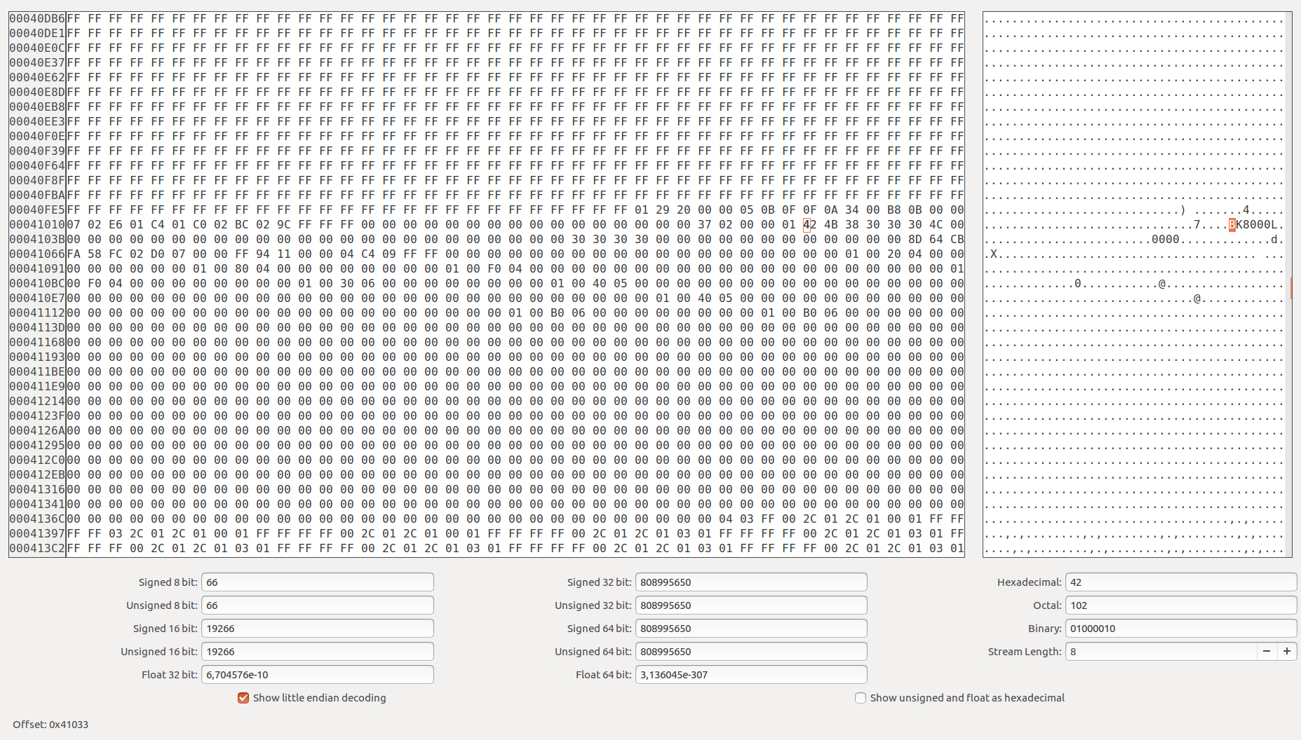
search for asci string BK8000L, change it, save and flash:
./flashrom --programmer serprog:dev=/dev/ttyUSB0 --read BK8000L.flash
flashrom v0.9.9-r1955 on Linux 4.4.10-040410-generic (x86_64)flashrom is free software, get the source code at https://flashrom.org
Calibrating delay loop... OK.
serprog: Programmer name is "frser-duino"
serprog: requested mapping AT45CS1282 is incompatible: 0x1080000 bytes at 0x00000000fef80000.
Found FMD flash chip "FT25H04" (512 kB, SPI) on serprog.
===
This flash part has status UNTESTED for operations: PROBE READ ERASE WRITE
The test status of this chip may have been updated in the latest development
version of flashrom. If you are running the latest development version,
please email a report to flashrom@flashrom.org if any of the above operations
work correctly for you with this flash chip. Please include the flashrom log
file for all operations you tested (see the man page for details), and mention
which mainboard or programmer you tested in the subject line.
Thanks for your help!
Reading old flash chip contents... done.
Erasing and writing flash chip... Erase/write done.
Verifying flash... VERIFIED.
solder flashchip back on module, power it and enjoy ;)
UPDATE 2019
No need to desolder chip, using this CH341A adapter [this one], I succesfully read/write chip, only requiremet is reset of module to be puled to ground (Credit goes here).

output of flashrom:

nail@sid:~/src/flashrom$ sudo ./flashrom --programmer ch341a_spi --read dump11.bin
flashrom p1.0-86-gad8db8c-dirty on Linux 4.4.10-040410-generic (x86_64)
flashrom is free software, get the source code at https://flashrom.org
Using clock_gettime for delay loops (clk_id: 1, resolution: 1ns).
Found FMD flash chip "FT25H04" (512 kB, SPI) on ch341a_spi.
===
This flash part has status UNTESTED for operations: PROBE READ ERASE WRITE
The test status of this chip may have been updated in the latest development
version of flashrom. If you are running the latest development version,
please email a report to flashrom@flashrom.org if any of the above operations
work correctly for you with this flash chip. Please include the flashrom log
file for all operations you tested (see the man page for details), and mention
which mainboard or programmer you tested in the subject line.
Thanks for your help!
Reading flash... done.
nail@sid:~/src/flashrom$ sudo ./flashrom --programmer ch341a_spi --verify dump11.bin
flashrom p1.0-86-gad8db8c-dirty on Linux 4.4.10-040410-generic (x86_64)
flashrom is free software, get the source code at https://flashrom.org
Using clock_gettime for delay loops (clk_id: 1, resolution: 1ns).
Found FMD flash chip "FT25H04" (512 kB, SPI) on ch341a_spi.
===
This flash part has status UNTESTED for operations: PROBE READ ERASE WRITE
The test status of this chip may have been updated in the latest development
version of flashrom. If you are running the latest development version,
please email a report to flashrom@flashrom.org if any of the above operations
work correctly for you with this flash chip. Please include the flashrom log
file for all operations you tested (see the man page for details), and mention
which mainboard or programmer you tested in the subject line.
Thanks for your help!
Verifying flash... VERIFIED.
nail@sid:~/src/flashrom$ sudo ./flashrom --programmer ch341a_spi --write dump7.bin
flashrom p1.0-86-gad8db8c-dirty on Linux 4.4.10-040410-generic (x86_64)
flashrom is free software, get the source code at https://flashrom.org
Using clock_gettime for delay loops (clk_id: 1, resolution: 1ns).
Found FMD flash chip "FT25H04" (512 kB, SPI) on ch341a_spi.
===
This flash part has status UNTESTED for operations: PROBE READ ERASE WRITE
The test status of this chip may have been updated in the latest development
version of flashrom. If you are running the latest development version,
please email a report to flashrom@flashrom.org if any of the above operations
work correctly for you with this flash chip. Please include the flashrom log
file for all operations you tested (see the man page for details), and mention
which mainboard or programmer you tested in the subject line.
Thanks for your help!
Reading old flash chip contents... done.
Erasing and writing flash chip... Erase/write done.
Verifying flash... VERIFIED.
nail@sid:~/src/flashrom$ sudo ./flashrom --programmer ch341a_spi --write dump11.bin
flashrom p1.0-86-gad8db8c-dirty on Linux 4.4.10-040410-generic (x86_64)
flashrom is free software, get the source code at https://flashrom.org
Using clock_gettime for delay loops (clk_id: 1, resolution: 1ns).
Found FMD flash chip "FT25H04" (512 kB, SPI) on ch341a_spi.
===
This flash part has status UNTESTED for operations: PROBE READ ERASE WRITE
The test status of this chip may have been updated in the latest development
version of flashrom. If you are running the latest development version,
please email a report to flashrom@flashrom.org if any of the above operations
work correctly for you with this flash chip. Please include the flashrom log
file for all operations you tested (see the man page for details), and mention
which mainboard or programmer you tested in the subject line.
Thanks for your help!
Reading old flash chip contents... done.
Erasing and writing flash chip... Erase/write done.
Verifying flash... VERIFIED.
*originaly I use flashrom 0.9.9 + apply my patch [5]
[1] http://famousconnections.eu/wp-content/uploads/2017/10/FT25H04.pdf
[2] https://www.flashrom.org/Supported_programmers
[3] https://github.com/tomaskovacik/flashrom
[4] https://github.com/tomaskovacik/kicad-library/raw/master/library/datasheet/F-6188_BK8000L/BK8000L.flash
[5] https://github.com/tomaskovacik/kicad-library/blob/master/library/datasheet/F-6188_BK8000L/flashrom_patch_for_FT25H04_support.patch


