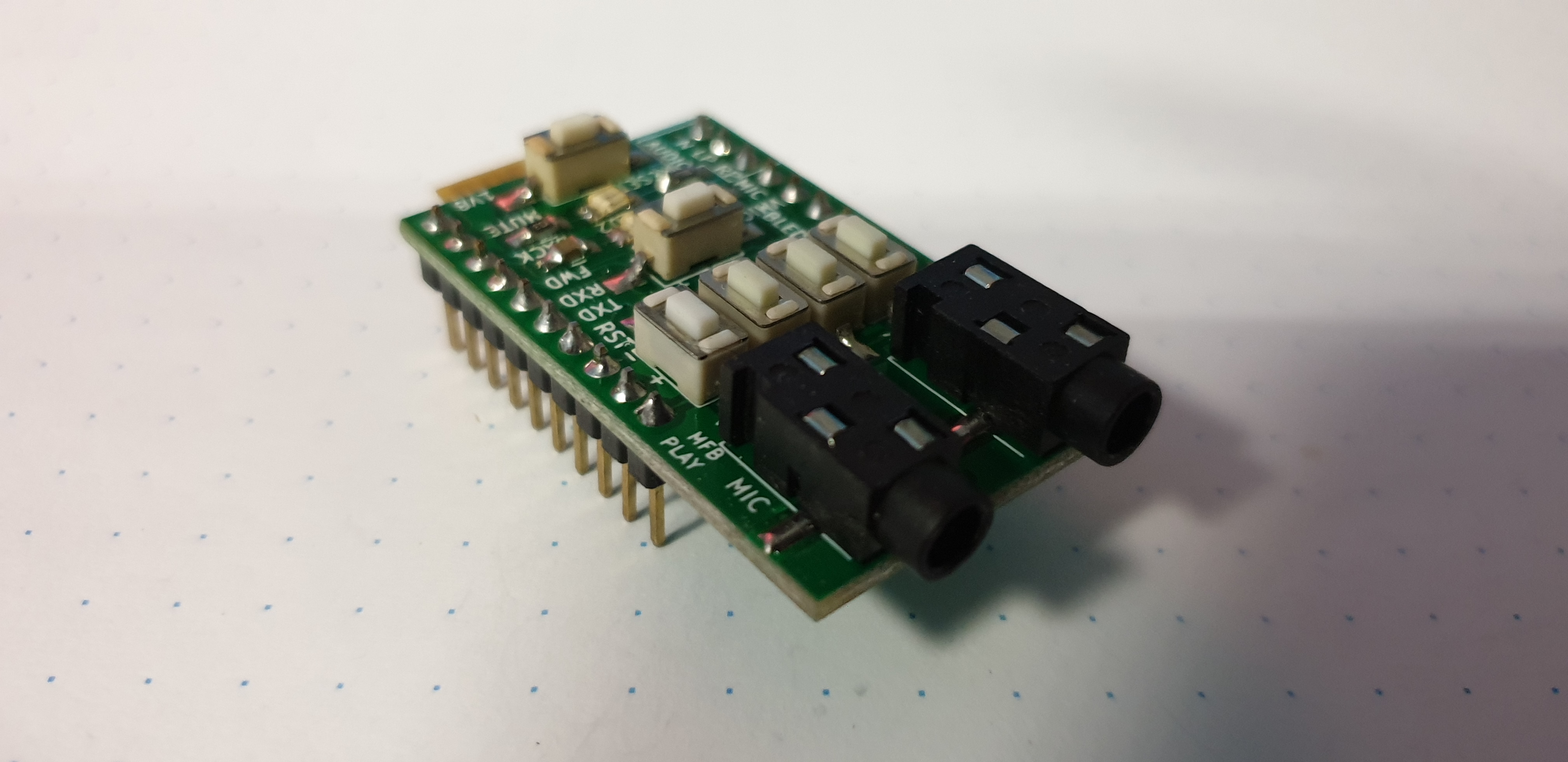
UPDATE: simple boards are for sale (1Euro for board + shipping), also asembled emulators + simple cable with jack (tested wvcdpic + audio cable = 10euros + shipping ), contact me on email if you are interested, also I can send preprogramed pic +2E
originaly this was on fritzing project page. There is lot of "files" so i make it clear here, I hope:
whole project is build around www.k9spud.com/vwcdpic/ project (mirror,mirror of devel site) , which was realease under gpl (2 I thing ...)
There are 3 firmware version:
v1: for large 16pin pic ... don't care
v2:
for pic12f629
source code provided
serial output, easy to handle with arduino
has bug with serial comuniaction, selecting CD3,4,5,6 send always command 0xd3 (cd3 selected), but fix is sipple,fixed pic asm is on my github
is buggy(don't use it!) on blaupunkt chorus1 and concert1 not on philips concert1
v3:
for pic12f629
just hex
serial output but with bug in serial communication (can't fix, no source code)
is buggy(don't use it!) on blaupunkt chorus1 and concert1 not on philips concert1
I don't know what's real diffrence in v2 and v3 code, except used pins.
I use buggy version 3 of fimrware only for emulating CD changer, without controling anything else and fixed version 2 to comunicate with arduino, which then I used to controling HTC phone and BT module.
When I start to search about this, I found that guys form cz skoda forum are doing this fake changer, they add power control to "switching" permament +12V ...... so I take their design and used it. After some builds, and research how to use this emulator with old audi chorus unit, I realize that BSP452 which is used to switch and provide stable 12V on ACC pin is capable of 0.7A as minimum, so I remove whole "power switch" and drive it whole directly from radio ACC pin.
Also audio amlifier is better not to be used, lot of noise etc... I try a lot of shielding, koax kables and design , and then I just give up. Best is to use simple emulator made on universal board, just like next picture, and connect audio directly to coresponding pins on radio CD changer connector. If you relly want to use regural PCB go with smd version down there and just "cut" audio part.
Simple version
for compiling pic asm: gpasm xxxx.asm
for burning I use http://rweather.github.io/ardpicprog/
Separated audio ground filling, to try killing the noise comming from comunication PIC<->radio. but it don't fix it :(. This can be easy converted to "just emulator" version.
edit: after a while I connect audio ground with separate cable to chassis and it fix noise problem, so as always, problem was ground loop. ...
problem with this BT module is in handling incoming call (or its bug in my HTC) after "pickup" it disconected from phone.
only pic I have :)
currently im doing "sniffer" for pic version, so I can update shyd version of emulator on atmega. I do this because on chorus1 and concert1, there is som sort of bug, which some time lock radio in strance mode, when radio still send one command and do not want to recognize fake changer :)
ATMEGA version
based on SHYD work, ported to arduino (ATMEGA168,328 and also works with ATMEGA8 -1$ on ebay). Works with 16MHz Xtal and also with internal 8MHz RC oscilator (tested) - set CPU_SPEED to cpu clock value in MHz more about this in newer post
When writing to the cluster, no external components are required,the cluster has all these components inside.
I think, this apply for pre-CAN-BUS cars only, check sticker on your radio, if there are 3pins labled ENA DATA CLK in middle section of mini-iso connector:
some 2000 models can be switched from canbus to this 3lb protocol.
From
schematics, difrence between chorus and concert which has CD changer
input, is just few parts and enable CD-changer by coding as in here. Parts need to be soldered on main board to
enable are this:
After this, you need CD changer emulator
and simple circute, which emulate "mode" button press. For so small
project is perfect attiny25/45/85 actualy 85 is cheapest one. For attiny
support in arduino, follow this tutorial. Sketch for tiny:
If subwoofer and rear speakers not working (avant version):
While radio is ON check if ther is 12V as red marks show. If so, check if there is a short like yellow marks show, if there is no short while 12V is in place, that means, relay is not working, change it or make permanent short between yellow solder joints.